
Companies that develop fan systems for the HVAC market have a variety of requirements to consider; chief among them are performance and size. Achieving performance targets is the first order of business, but rightsizing the motor for the task at hand can lead to additional benefits.
Finding the right motor is critical for delivering on these requirements at the systems-level.
Here, we’ll:
-
- Walk through the motor selection process
-
- Dive into a few central ways motor design and selection can support overall fan system performance
-
- Provide insights surrounding motor rightsizing and how it can be beneficial in applications with a large number of fans or fan arrays (e.g., data centers)
Unlocking the Potential in the Motor Selection Process
The motor selection process starts early in the fan system design cycle. Performance requirements are dictated by customers in the form of flow targets (cfm) and pressure targets (in-wg). With that knowledge, the fan design team makes two important selections:
-
- A fan model that can deliver on flow rate expectations
-
- A motor with the requisite torque and speed to drive the fan at the customer’s desired operating parameters
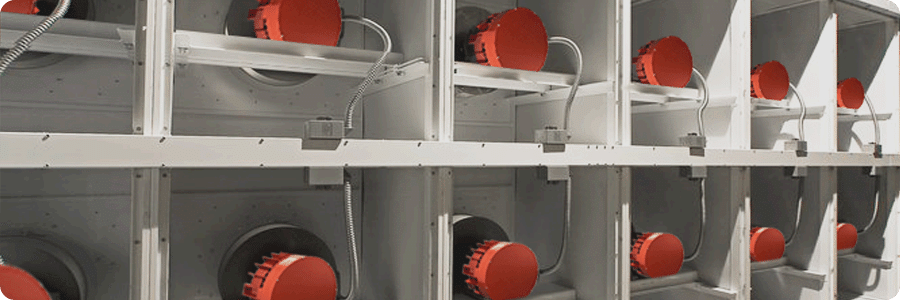
Take the example of a data center. These facilities require well-designed fan systems to cool servers, maintain airflow between aisles and sustain appropriate humidity levels.
Our example data center application requires an operating point of 10,000 cfm at 2.5 in-wg of static pressure. The fan OEM uses that operating information as input for an in-house selection software that specifies an appropriate fan model and a motor that provides the brake horsepower (bhp) and motor speed (rpm) required to drive that fan. Rather than using a software tool, for illustrative purposes, we’ll use a fan curve.
Based on our example application parameters, fan model ABC was selected. Once fan model selection is complete, the fan curve, shown in Figure 1, is used to determine the combination of motor power and speed that can deliver the requisite operating conditions.
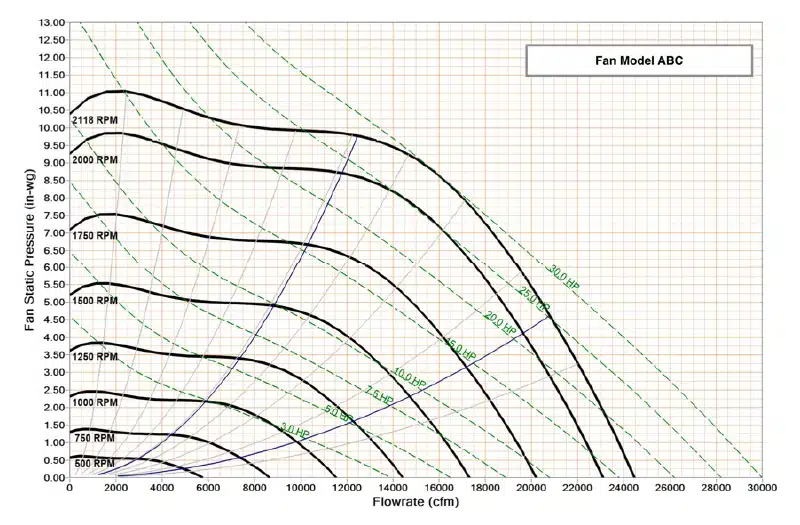
In this example, assume the motor that meets customer requirements is a 5.4 hp motor at 1208 rpm with a torque requirement of 23.5 lb-ft (31.8 Nm). Knowing the fan’s power and speed requirements are accounted for, the fan OEM looks for a motor with the best efficiency throughout the fan’s operating range.
Prioritizing Fan Performance and Efficiency in Motor Selection
Motor efficiency benefits the entire fan system, so motor selection is central to energy savings—a focus area for customers and regulators alike. Matching a motor’s peak efficiency with a fan system’s peak efficiency provides the optimal efficiency for the system overall. Motor efficiency curves are helpful for visualizing motor performance across a variety of loads and speeds.
Assess Motors at Partial, Optimal and Full Loads
While it’s important to know the system’s optimal duty point, there will be times when the motor runs at full or partial loads, so it’s equally important to consider how it’ll perform under those circumstances. For instance, when cooling demand decreases in an office building over the weekend, the system may run at a partial load. Alternatively, in a redundancy situation where one fan in an array fails, the others will work harder to maintain airflow and static pressure.
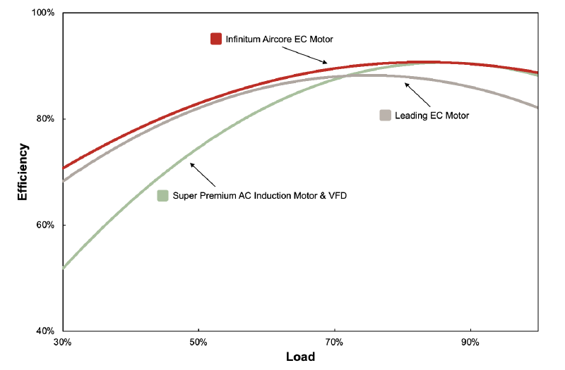
Understanding the reality of fan system operation, Infinitum motors are designed to deliver some of the highest levels of efficiency on the market across a wide range of load conditions and speeds. A flat efficiency curve across loads means the motor delivers higher levels of efficiency during the actual operating conditions of the fan system. Figure 2 shows that the Infinitum Aircore EC motor delivers better efficiency than two leading choices: Super Premium AC Induction Motor & VFD and a Leading EC Fan Motor.
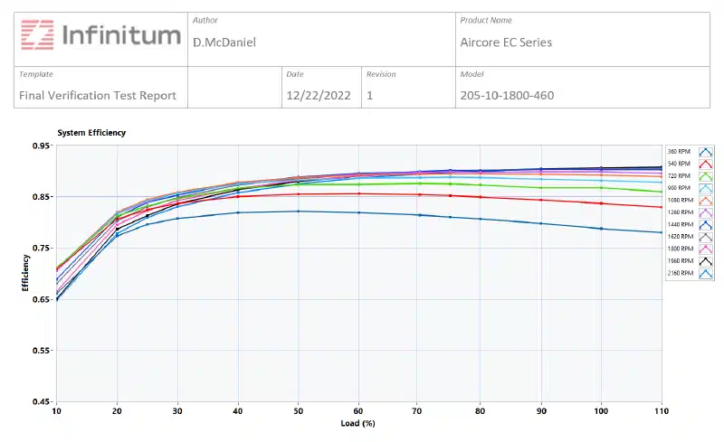
Infinitum’s Aircore EC is built with an innovative PCB stator architecture which eliminates core losses and delivers high efficiency levels. The Aircore EC is a motor system that includes the motor and an integrated variable frequency drive (VFD). Each Infinitum motor system comes with a “Final Motor Verification and Test Report” which includes a motor efficiency curve like the one shown in Figure 3.
How Infinitum Supports Motor Selection for Fan System Applications
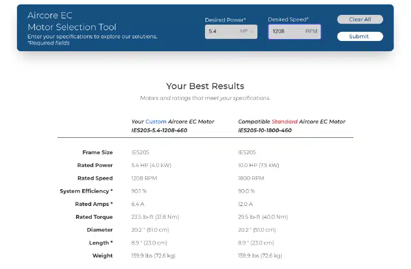
To support the selection process, Infinitum offers the Aircore EC Motor Selection Tool to help fan OEMs select a properly optimized motor to fit their fan system. Returning to our fan system example, Figure 4 shows which motors best fit the 5.4 hp at 1208 rpm combination established using the fan curve. In this case, the motor selection tool provided two options. Fan OEMs can compare these motor recommendations, including rated power, rated speed, motor system efficiency, rated amps and rated torque.
Then, fan OEMs select either:
-
- A customized motor system configuration that is provided with a certified nameplate complete with the custom selection’s FLA, rated power, and rated speed
-
- A motor with standard settings and nameplate that can be operated at the specified operating point
Custom Nameplating Services
With custom nameplating, motors like Infinitum’s can be rated with a lower amp rating. The motor selection tool includes the rated amps for each motor option. For the 5.4 hp motor, rated amps is 6.4 A. For the 10 hp motor, rated amps is 12.0 A. A lower input current allows the customer—in our case, a data center designer—to save on upstream electrical infrastructure costs by reducing the amount and size of wiring, circuit breakers and transformers.
In our example, input current savings would amount to 5.6 amps per motor. In a fan array composed of six fans, this amounts to 33.6 amps. The savings become significant when you consider that data centers usually require many fan arrays to prevent servers from overheating, allowing them to stay online for long periods of time. If, for example, the data center required 100 fan arrays (comprised of six fans each), the electrical infrastructure for the 5.4 hp motors would need to handle 3,840 amps (100 arrays x 6 fans x 6.4 amps) where the 10 hp motor would drive a requirement of 7,200 amps (100 arrays x 6 fans x 12 amps).
Size Optimizations at All Levels of Motor Design
Another important factor in motor selection is size. For many fan applications, the length of the motor is a crucial dimension in determining the width of the cabinet that houses the fan system. The Aircore EC motor series is shorter in length than an AC induction motor with comparable horsepower, due to its axial-flux motor design. For example, with the integrated VFD, a 10 hp Aircore EC motor at 1800 rpm is 8.9” in length, including the motor and drive. At 19.8”, a comparable AC induction motor from TECO-Westinghouse (10 hp / 1800 rpm) is more than twice the length. Optimizing the cabinet width to be as small as possible saves precious space in the data center mechanical room and simplifies transport and installation.
Because of the axial-flux motor design, the Aircore EC has a larger diameter than the typical AC induction motor. The larger diameter can be advantageous for centrifugal fan applications if it is close to the diameter of the wheel; in that case, there is less air turbulence through the fan array, so there is smoother airflow through the fan.
In summary, as we saw with our data center example, the ability to pinpoint the motor that best fits the actual power and speed needs of a given fan application will provide downstream benefits. Focusing on performance as early as the motor selection process results in reduced input power per motor, meaning fewer electrical infrastructure needs, reduced energy consumption and significant financial savings up front and over time.
Talk performance requirements with our team or try our motor selection tool.